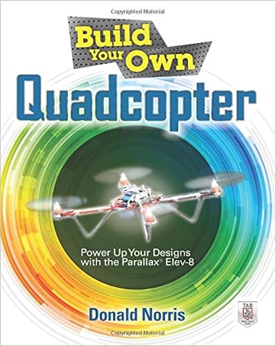
Build Your Own Quadcopter: Power Up Your Designs with the Parallax Elev-8
Language: English
Pages: 368
ISBN: 0071822283
Format: PDF / Kindle (mobi) / ePub
Build a custom multirotor aircraft!
Build and customize radio-controlled quadcopters that take off, land, hover, and soar. Build Your Own Quadcopter: Power Up Your Designs with the Parallax Elev-8 features step-by-step assembly plans and experiments that will have you launching fully functioning quadcopters in no time. Discover how to connect Elev-8 components, program the microcontroller, use GPS, and safely fly your quadcopter. This fun, do-it-yourself guide fuels your creativity with ideas for radical enhancements, including return-to-home functionality, formation flying, and even artificial intelligence!
- Understand the principles that govern how quadcopters fly
- Explore the parts included in your Parallax Elev-8 kit
- Follow illustrated instructions and assemble a basic 'copter
- Connect the Parallax chip to a PC and write Spin and C programs
- Build radio-controlled systems that minimize interference
- Add GPS and track your aircraft through Google Earth
- Beam flight information to smartphones with WiFi and XBee technology
- Mount cameras and stream real-time video back to the ground
- Train to safely operate a quadcopter using flight simulation software
How to Make Books: Fold, Cut & Stitch Your Way to a One-of-a-Kind Book
Totally Cool Nails: 50 Fun and Easy Nail Art Designs for Kids
Handmade Home: Simple Ways to Repurpose Old Materials into New Family Treasures
Wire + Metal: 30 Easy Metalsmithing Designs
Chassis top plate in a later step.) Refer to Figure 3.25 for the items needed from your Elev-8 Airframe and Hardware kits. FIGURE 3.25 Attaching motor/boom assemblies to the bottom chassis plate. 1. Locate the correct mounting holes in the bottom chassis plate to use for the motor/boom assemblies. 2. Position a motor/boom assembly (item 2) on the bottom chassis plate (item 3). The boom tube rests on top of the plate with the motor axle pointing upward, and the LED tape facing downward. The.
Concept.) Refer to the ESC block diagram shown in Figure 5.9 as you read the description of how an ESC functions. FIGURE 5.9 ESC block diagram. The heart of modern ESCs used in quadcopter projects is the Atmel ATmega8L microcontroller unit (MCU), which is a flash-memory-based, 8-bit microprocessor with some peripheral-control components. Table 5.1 shows some of the ATmega8L key specifications. TABLE 5.1 Key ATmega8L Specifications These specifications reveal a very capable controller that.
Into a specific bit position, which is the purpose of the bitwise decode instruction “|<.” The above bit operation results in the following binary bit pattern being stored into the ServoPin variable: %00000000 00000000 01000000 00000000 This bit pattern is copied into the cog’s dira register, thereby enabling pin 14 as an output, which is the desired outcome. A Brief Introduction to the C Language You should probably appreciate a simpler alternative to creating fast code after going through.
DATA indicates to the tokenizer that this information will be stored in EEPROM. L#P# is the line number (1 or 2) and position number (1–16) where the first character of text is to be located in the LCD. LENGTH is the number of characters that follow inside the quotation marks. For the above example, this program line might look like this: When the DSP_TEXT subroutine is called after the message pointer MSG is set to the string’s label: MSG = T_STRG, the text message “STRING INFO” is displayed at.
Beginning at character position 10 in line 1 of the LCD: 2. To display the number 456.7 beginning at character position 3 in line 2 of the LCD: Communicating with Peripheral Modules The example programs each have slight differences in the data acquisition subroutines and should be examined closely before writing your own. The ECH-4 is especially unique, since it uses a single bidirectional serial bus. The basic procedure is described in the following section. Writing to a Peripheral Module.
